
AJAX LEADER
OK - I know this isn't strictly a boatanchor. But it did come from a boat! This marine transmitter/receiver was acquired at one of many "container" sales organised by VMARS (Vintage and Military Amateur Radio Society) to dispose of the lifelong radio collection of the late G3TFC. John had amassed an incredible amaount of equipment over the years and VMARS took on the sad duty of ensuring that as many items as possible went to a good home. As can be seen, the set appears in reasonable condition (at least all it's knobs were present) and I was confident that, with a bit of elbow grease, it could be cosmetically restored to it's former glory!

Taking it out of it's case, however, it soon became clear that bringing it back to operational condition would be more of a challenge. There appeared to be a large chunk missing!
 In
it's former life, this equipment had been designed to run from a 12V DC supply.
The receiver was fully transistorised as were the early stages of the
transmitter and the modulator. The PA stage, however, used a pair of TT22 valves
to achieve a modest 50W output and these were designed to work with a supply
voltage of 700V. This was obtained using a solid state inverter and this was the
chunk that had been removed by a previous owner. In some ways, I was relieved to
discover this. Initially, not having any documentation, I had thought that it
was the modulator that had gone awol. I could construct a high voltage power
supply but the loss of the modulation transformer would probably have stopped
the project in its tracks.
In
it's former life, this equipment had been designed to run from a 12V DC supply.
The receiver was fully transistorised as were the early stages of the
transmitter and the modulator. The PA stage, however, used a pair of TT22 valves
to achieve a modest 50W output and these were designed to work with a supply
voltage of 700V. This was obtained using a solid state inverter and this was the
chunk that had been removed by a previous owner. In some ways, I was relieved to
discover this. Initially, not having any documentation, I had thought that it
was the modulator that had gone awol. I could construct a high voltage power
supply but the loss of the modulation transformer would probably have stopped
the project in its tracks.
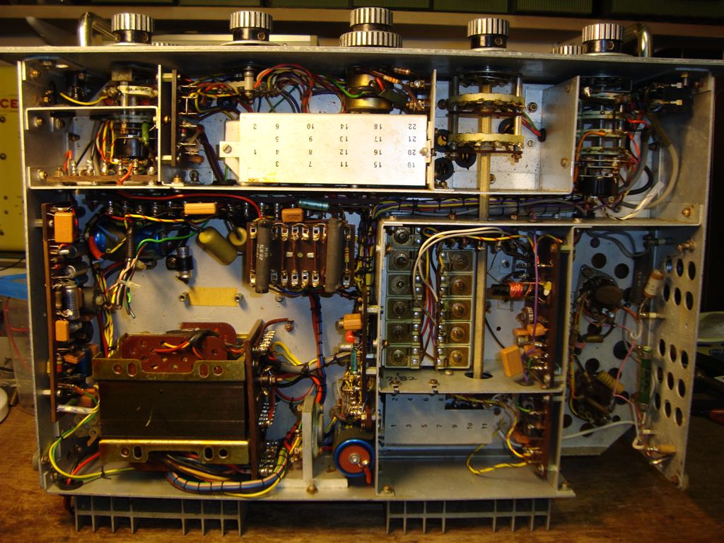
Looking under the chassis, however, I eventually discovered that what I had thought was the inverter transformer was, in fact, the mod transformer. Although various other bits had been removed (as evidenced by the cut off loom stubs), it looked as if the modulator was all there.
Thanks to VMARS members, I managed to get hold of circuit diagrams of the transmitter and receiver. This confirmed the above deduction and, much to my relief, indicated that the other missing parts were not essential for amateur radio operation. I couldn't see much call for a warbling alarm signal!
I tackled the receiver first. Actually it didn't require much fettling. At first I thought there was a serious problem in the IF but it turned out to be a sticking relay which was permanently connecting a narrow audio filter for CW reception. The only other problem was non-operation of the RF gain control which was fixed by replacing an open circuit Germanium diode. The forward AGC doesn't quite manage to handle very strong MW signals on a long aerial but I don't consider that to be a real problem.
Now the early stages of the TX are supposed to be powered from an isolated 20V (?) supply from the inverter. I didn't plan to have this supply so I simply used the 12V supply and tweaked the drive preset to give a bit more gain. This did mean that I had to configure the whole thing as positive earth, however, so I would have to be a bit careful not to short things out. A couple of 12V relays were added to handle the R/T changeover as these had originally been located in the inverter.
I didn't have any TT22's to put in the PA so I used a pair of 6146's. This just required a swapping a couple of pin connections and arranging a 6.3V heater supply. As various other modifications had already been done to the set, I considered this to be acceptable. Eventually, a kind VMARS member let me have a couple of TT21's and so the valve bases where restored to their previous connections. The above chassis view looks a much better with "proper" sized valves!
A high voltage power supply was quickly lashed up and, with the help of a 12V battery, the rig was given a tentative trial run on the 3615kHz VMARS Saturday morning net. Signal reports were fairly encouraging although the modulation was apparently rather bassy. This was soon fixed by significantly reducing the value of a coupling capacitor in the microphone preamplifier stage and subsequent reports have been very good.

Update - July 2019
A couple of years ago, the separate high voltage power supply for the AJAX was robbed for use with my ART13 transmitter. Subsequently the AJAX had not been used and I was considering "moving it on", possibly at another VMARS auction. Although it worked well enough, being unable to operate it as intended from a single 12V supply always rankled slightly and the chances of finding a replacement inverter were pretty slim.
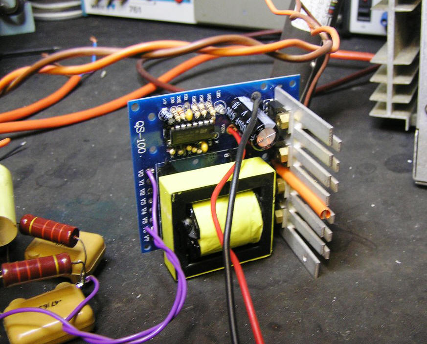
A recent search on Ebay, however, revealed that cheap HV inverters were available in abundance and one in particular looked like it might be a suitable candidate. It originated, of course, in China and claimed to be capable of producing 500W at 380V AC from 12V DC. The asking price of less than a tenner made it a no-brainer - the cost of the MOSFETs alone would be more than that! Even if the 500 watts was a bit of an exaggeration, I only actually needed about 75. So, once the slow-boat had made its way around the world, I had the basis for a replacement high voltage supply that could be built into the AJAX. Powering up the inverter on the bench it was soon clear that the output was a square-wave, so to get to around 700V I used a full wave voltage doubler using fast recovery HV diodes (UF4007). At 20kHz, a simple LC filter gave a ripple value of less than 500mV at the required load current. No heat sinking was provided on the MOSFETs so a couple of finger strips were cut from an old ATX power supply. Even at over 100W output, the FETs were only slightly warm to the touch after 5 minutes.
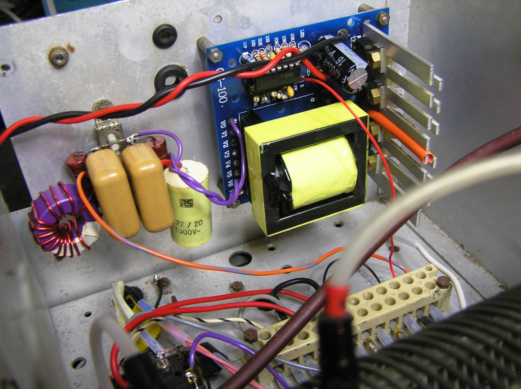
Fitting the inverter to the AJAX didn't present any problems - It was clearly a good deal smaller than the original part. I decided that the back wall was the most practical location. There was plenty of space available for the voltage doubler and LC filter on a small tag-strip thanks to the low values required at 20kHz. After double checking that I hadn't introduced any shorts due to the +12V chassis, power was applied without incident, the inverter being held off by its enable line, hence no interference on the receiver. Switching to transmit enabled the inverter and the transmitter produced a healthy 50W. I had a look at the spurs at multiples of the inverter frequency and they were all down at least 50dB so it was tested on air and received good reports.
As explained previously the TX driver stage was reconfigured to run straight off the +12V due to the lack of the +20V supply from the original inverter. This is still in place at present. I just have to be a bit careful not to short the chassis to the 12V negative - not a real problem as I shall be running from an isolated lead acid battery. Amazingly, the new inverter does have an isolated 18V winding, so it should be possible to re-instate the original configuration. All I have to do is remember what exactly I did so that I can reverse it!